
1 Introduction
In recent years there has been a large increase in offshore oil and gas exploration activities. About 60% of the work is being performed with jack-up drilling rigs (Dennes, 1984). Some variabels must be considered i.e. rig dimension, jack-up rig type, and the seabed morphology. This research is focused on determination of the seabed morphology, so seabed mapping must be conducted to make sure
| Received, Revised, Accepted for publication |
the rig emplacement process is safe. Indonesia is an archipelagic country, which consists of more than 13.466 islands and has approximately 3.7 millions barrel oil reserves. Indonesia needs some researchers and experts in sea mapping field to support the national infrastructure development, especially development in the coastal and ocean areas, scoping either the sea surface, seabed surface or subseabed surface. This research will focus on the discussion about the procedures in moving and placing on Mobile Offshore Drilling Unit (MODU) which named Jack-up Drilling Rig. This research will focus on the description of the seabed morphology which was obtained by single and multibeam echo sounder and how the equipment works. The result will be combined with another data such as side scan sonar, sub-bottom profiler, magnetometer, and soil sampling with soil boring method. This whole process is considered to be done so that the position of the jack-up drilling rig's legs could be placed and fitted around the proposed area before.
Also to decrease the risk that may occur due to the seabed and sub-seabed condition, such as (Basuki, 1986): A disadvantage seabed soil conditions, some gas pockets that contain a high pressured gas, incompatible seabed topography condition, Some things that has been existing on the seabed and may cause a danger. Information of bathymetry and seabed morphology information is important in order to make a rig's maneuver design and which area is feasible enough for the jack-up type drilling rig's emplacement. This research may provide some informations about seabed topography and its features, and also the perspective from the geoscientist to understand what kind of seabed condition that appropriate for this kind of drilling rigs. This research may result a proper procedure to be used in seabed clearance survey in seabed morphology mapping for jack-up drilling rig emplacement. The research questions are what is the seabed topography and morphology within the case study area and what is the comparison between the safe area and area that has obstructions. Does the study area, including the proposed wells comply the jack-up drilling rig emplacement criteria. The objectives of this research are to determine the seabed morphology at and around the proposed well location with accurate water depth, to assess shallow geotechnical condition for the jack-up drilling rig's emplacement combined with the soil boring results, to assess the shallow sub-bottom geological condition including the presence of any shallow sub-bottom anomalous such as shallow gas and/or shallow faults.
2 Data and Methods
Methodology of the research is literature study and data processing. The methodology started from studying about site survey activity in offshore area. The literature and references was sourced from related research, international and domestic text books and research papers, also some research in the internet. The literature study interspersed with discussions with the supervisors and practioners in the industry. The research continued to data procurement stages which was provided by PT. Pageo Utama. The data is raw data from acquisition activity and some geophysicist's interpretation results. Started from multi-beam echo sounder data calibration and continued to filtering. In this process, the sounding tracks must be suitable to particular calibration factor. After multi-beam echo sounder data processing, the research continued to single beam echo sounder data processing and side scan sonar images mosaicking and make recommendation for rig's manuever and emplacement based on bathymetric information from echo sounder, seabed features information from side scan sonar image, sub-bottom features from sub-bottom profiler and soil boring, and magnetic anomalous from magnetometer. The methodology implemented in this research can be seen in Figure 1.
2.1 Site Survey
In seabed morphology mapping, site survey is one of the most important survey phase that must be done. Site survey are performed to minimise the risk of harm to personnel and equipment, and to protect the natural environment (OGP, 2013). Every site surveys have their own objectives that is to identify all possible constraints and hazards from man-made, natural and geological features which may affect all of the operational or environmental integrity of a proposed drilling well operation, and also to allow appropriate operational practices to be put in place to mitigate any risks identified. In addition, the proposed site survey area that contains the proposed wells should be in adequate coverage to plan any potential relief well locations and provide sufficient data to assess the fully potential top-hole drilling hazards at these locations. Site Survey is performed to identify any sub surface objects which would damage the installation of an underwater structure, to identify shallow gas areas prior to a drill rig entry, to identify with the means of an Remotely Operated Vehicle (ROV), hazardous objects on the seafloor which may endanger the installation of underwater structures, to identify with seismic equipment the sub strata of the seabed to identify faults for the determination of mineral resources, investigate slope stability.
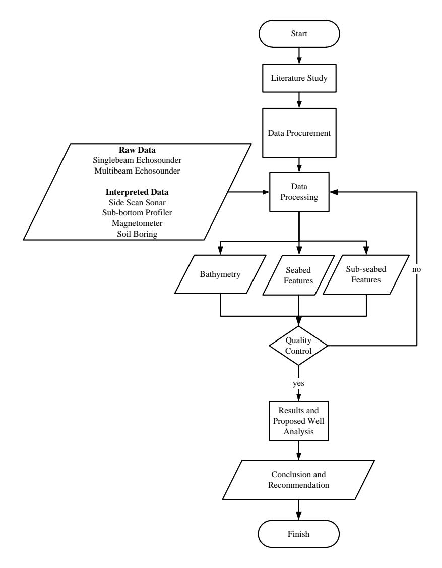
Figure 1. Research Methodology Flowchart
A site-specific survey for a production platform, including jack-up drilling rig, must cover at least the area within a 1,000 meter radius of the proposed drilling rig or the platform location because in jack-up drilling case, technically the spudcan (As shown in Figure 2.4) will make a contact with the seabed within 400 meter radius of the proposed well, also 100 meter beyond the furthest anticipated anchor location for a drilling rig, derrick barge and pipe lay barge, whichever is greater. It might be required to do the survey in a larger area if sensitive habitat or other conditions need to be evaluated. Primary and tie line spacing for all
acoustic data acquisition systems for a platform site survey may not exceed 150 meters intervals, depending on the water depth.
Based on Oil and Gas Producers Standard Guidelines for the conduct of offshore drilling hazard site survey report no. 373-18-1 April 2013 version 1.2, the scope of site survey must include a review of all seafloor and geological condition to at least 200 meters depth below the preferred setting depth of the first pressure containment string or to a depth of 1000 meters below the seabed, whichever is greater. Identification and assessment process of all relevant geological features is suggested to be performed within the context of a geological model that takes into account for depositional and post-depositional processes. The output of the site survey activity is a report that must include a discussion of all relevant geological and/or man-made features that have a direct bearing on operational risk. Generally a site survey activity process may be considered to consist of four phases as shown in Figure 2.
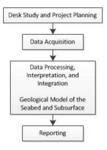
Figure 2. Site Survey Process (OGP, 2013)
From Figure 2 above, the desk study should be considered as an integral part of the project planning process. In this phase, some decisions will be made regarding new data collection and which type of data requirement. In deep water areas, according to OGP (2013) the water area that has >150 meters depth, the desk study and any ensuing acquisition may need to address a semi-regional scope to consider topographic or geological matters that may be a threat to operations from outside of the direct area of proposed operations. The next phase is the acquisition of new data coverage. All the existing and the new data that has been processed or reprocessed to improve their value, and interpreted to produce an integrated geological model of the seabed and subsurface conditions are done in the third
phase. The last phase holds the integrated report that describes the condition and operational risk identified across the site and – specifically – at the proposed drilling/well location
2.2 Jack-up Drilling Rig
Offshore drilling rig commonly are divided to fixed platforms, compliant towers, semi-submersible platform, jack-up drilling rig, drill ships, floating production systems, and spar platforms. They are divided based on the capability to accommodate the water depth condition. The type of drilling rig discussed in this research is the jack-up type one or also called jack-up drilling rig. Jack-up rig is a mobile drilling rig and has a long structures which is lowered to and into the seabed and raising the rig's body out of water. This rig is a type of the many other rig's types and it operates only in offshore area and need bottom supporting system to support the body (Figure 3).
Figure 3. Typical Jack-up Drilling Rig Unit (Casidy, 2011)
The main characteristics of this type is jack-up rig has the capability to adjust its elevation until it fits the water depth in the drilling activities location. Jack-up will only operate in shallow water area with average water depth within 90-110
meters and maximum depth of about 150 meters (Chakrabakti, 2005). Therefore, the water depth in which a rig can operate will depend on the extent of the penetration of its leg into the seabed and the air gap required at the given location (Dennes, 1984).
Jack-up drilling rig first is towed and assisted by around 2 up to 4 tug boats. In this phase, the jacks down until the hull is in contact with the water and then free to float under tow to the next installation location. Before moving the unit, it must be clear what geodetic datum is used in determining the drilling target position. The datum might be different with the one the positioning system is using considering the original seismic data was done a long time ago. It is important to know the transformation parameters from the vessel's positioning system is used to geodetic datum that used while planning the drilling programme. When a rig arrive at a drilling location, the jack-up legs will be mechanically lowered until a contact wih the seabed is made and nominal penetration of the legs has been achieved. Contact is made within radius 400 meters from the proposed drilling well and the legs are dragged until they reach the fixed location. After the position of the unit is cross-checked, the leg are jacked down and penetrate going through the seabed into the sub-seabed. The legs will keep penetrating until sufficient bearing resistance is encountered by the footings, the hull will start to rise clear of the water.
To make the route design, the selected route must be the safest and shortest possible. The jack-up drilling rig's stability will be varying depend on the cantilever type in correlation to the behavior and mechanical characteristics of the seabed soil. The soil investigation must be held before the jack-up unit is installed. In the jack-up drilling rig emplacement process, some things need to be considered related to the seabed conditions itself. Information about characteristic of the seabed is substantial to know about seabed and sub-seabed geological condition, such as stratigraphy, shallow faults, sediment strength, old river and glaciers, and water bottom anomalies and non-geological condition such as manmade objects. The location must be spared from those conditions so they do not endanger the rig during the emplacement and production process. There are four conditions to determine the location of the jack-up drilling rig in order to be feasible for the emplacement phases (Mandasari, 2012) i.e. if the location is a new drilling location, then the conductor (well) location and the position of any subsea structures (debris, existing pipeline and/or subsea cables) around the platform must be considered and a soil investigation survey may be held within the location, If the location has already been used by the same structure before, then it is recommended to use the same position as the existing jack-up footprint, If the location is an open sea drilling, the existing subsea structure, also the bathymetry, any slope or channel around the drilling location must be considered to know whether the seabed is relatively flat or not, also the soil investigation as a supporting data to know the sub-seabed geological condition, Within proposed wells must have maximum 150 meters water depth and no existing features that may endanger the rig's structure.
2.3 Acquisition Instrument and Data Processing
Echosounder is an equipment used to get information about the topography of the seafloor that describes the closest condition to the reality by measuring the depth of the sounding points and horizontal position on the sea surface. Echosounder works by utilizing the wave propagation characteristics in the vertical direction from the sea surface down to the seafloor. The sea depth may be determined through the following relation:
\[d = 0.5 (V. \Delta t) \tag{1}\]
Where d is a measured water depth, V is sound velocity in the water, and ∆t is the the time interval between the emitted and received sound wave. The echosounder used a single beam is called singlebeam echosounder (SBES) and another that used multi beam is called multibeam echosounder (MBES).
Side scan sonar is used to produce images of the sea-bottom, which in turn are used for geological investigation and the search for objects like wrecks, mines and pipelines. Side scan sonars are designed to provide "acoustic image" of the seabed, with high definition. Side scan sonars are used to give a near-visual representation of the geological faces and also give general indications about the nature of the water-bottom interface, directly linked to the "reflectivity" of the signal. For example, a soft sedimentary bottom (silt, mud) will send back little energy because of its low impedance contrast with water and its interface smoothness, on the other hand a rocky or gravelly bottom will have the opposite effect, with strong impedance contrast and high roughness (Lurton, 2002). Side scan sonar usually is used for object detection like minerals, shipwreck, pipelines, cable lines and bottom rock classification like the sediment type, rock outcrop, sand suns, also for underwater constructions inspection activities. In general, side scan sonar system consist of three main components i.e. tow fish, transmission cable, and topside processing unit. Another supporting instrument is sub-bottom profiler that provide information about the sub-seabed layer, magnetometer that provides information about any existence of any metal object by measuring its magnetic anomaly, and soil boring that provides information of the soil condition.
3 Result and Discussion
The method used for the discussion is comparative verifying each other and discuss about five information, i.e. site bathymetry, seabed features, sub-seabed
features, magnetic anomalous, and geotechnical information within the research area. The single beam and multibeam echo sounder produce a bathymetry information, side scan sonar interpret a seabed feature information, sub-bottom profiler results sub seabed features information, magnetometer results a magnetic anomalous information, whereas the soil boring data will result the physical morphology of the research. Single beam echo sounder is used to validate the multibeam echo sounder processing result, and side scan sonar used to verify if there is any seabed objects. Magnetometer produce information about magnetic value and geotechnical is used to help the geophysicist in interpreting the subbottom profiler result.
3.1 Bathymetry
Bathymetry information in jack-up drilling rig emplacement is needed to obtain the description or topography of the seabed and also to know the seabed condition around the working area. The depiction of the seabed topography for jack-up drilling rig emplacement will be visualized as depth contour and/or also digital terrain model. Every depth information must have a horizontal position. In this research, the visualization will be a depth spot map with contour and digital terrain model from MBES survey and a survey lines from SBES survey. Positioning and bathymetric data acquisition must be done in a same time within the survey area, so in the same time the horizontal position of the depth spots can be obtainable directly.
Figure 4. Single Beam Echosounder Plotting Result
Figure 4 is the result of singlebeam echosunder. The survey main lines consist of 27 lines and the cross lines consist of 18 lines and the depth result is presented in meter unit. The depth points must free from any error and has been corrected. The high frequency must result a shallower depth value than the low frequency
because it penetrate less deep than the low frequency. Some depth value has the high frequency value deeper than the low ones. This anomaly may be happened due to the transducer's error while conducting the survey or the single beam transducer passed through an object. Ordinarily, the used data is from the high frequency transducer.
The multibeam echo sounder data was processed using QINSy 8.0 software belongs to PT. Pageo Utama. The data was in acquisition database format (raw data) and equipped with sound velocity profile which was observed by sound velocity profiler (SVP) instrument. SVP is also applying acoustic wave to observe the sound velocity in the water. The following depth spots has been reduced to chart datum, which is referencing to Lowest Astronomical Tide. Before processing the main line multibeam echo sounder data. The data must gone through a calibration process. The calibration results a calibration graphics so it can be analyzed how well the line chosen. The calibration results a deviation angle i.e. roll, pitch, and yaw angle. Multibeam echo sounder result from the processing is a multibeam echo sounder depth spots and Digital Terrain Model (DTM). Figure 5 is the picture of multibeam echo sounder depth spots which consist of thousands depth spots, and also the result of the DTM was exported in an image format as shown in Figure 6.
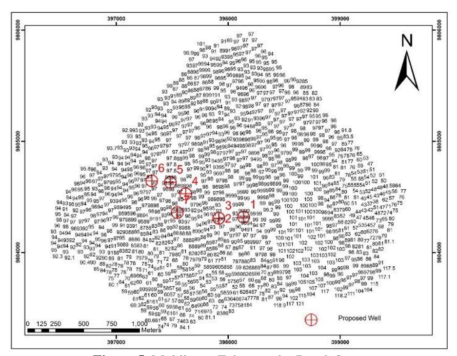
Figure 5. Multibeam Echosounder Depth Spots
Figure 6 below is the picture of the interpolated depth spots and exported to .tiff extension image. The red area is the shallower depth area whereas the darker blue color shows a deeper water depth. From this bathymetric map, the morphology can be interpreted that the red coloured area has more hazard potential for jackup drilling emplacement because it has an extreme slope changes and may endanger the rig construction.
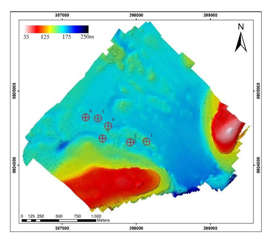
Figure 6. Multibeam Echosounder Image
3.2 Seabed Features
The result of side scan sonar in this research is a seabed images which depict the seabed features such as, the result of this research, coral outcrop and high reflectivity seabed. The result of side scan sonar is a result from interpretation and mosaicking process per survey line. The images was combined become a mosaic so the survey area can be depicted as a whole. The mosaic result in Figure 7 has already had coordinates because it is a georeferenced image and geotif formatted. Mosaic in Figure 7 consist of 50 side scan sonar images which overlaid each other. Figure 8 and Figure 9 may verify each other, because the multibeam echosounder image can also be used to interpret the seabed features.
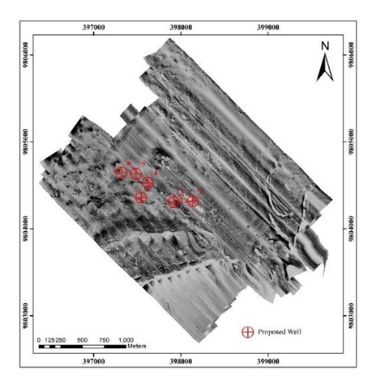
Figure 7. Side Scan Sonar Image Mosaic Result
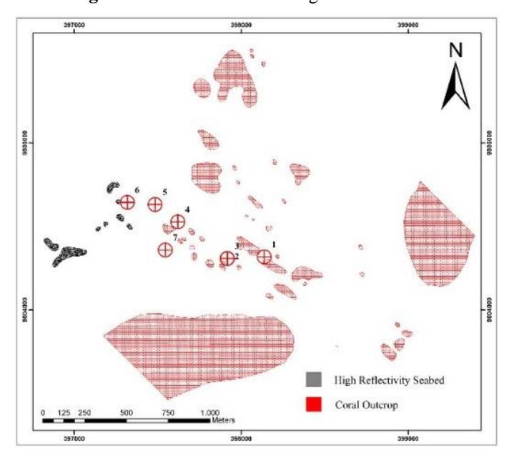
Figure 8. Seabed Features
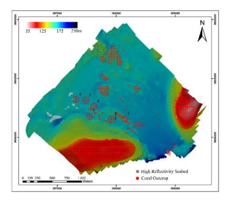
Figure 9. Seabed Features Overlaid to Multibeam Echosounder Image
3.3 Sub-seabed Features
The information of sub-seabed features is one of the supporting information in this undergraduate thesis. The information of sub-seabed features is provided by sub-bottom profiler and magnetometer, if there is any metal object on the seabed and presented in magnetic anomalous number. The sub-bottom profiler result is interpreted by the geophysicist to know whether there is any object or obstruction located below the seabed. Beside the sub-seabed features, jack-up drilling rig emplacement also need information about the soil structure provided by geotechnical survey, in this case, was held by soil boring activity. The soil boring must be interpreted by the geotechnical engineers to know the bottom soil condition.
4 Conclusions
The bathymetry within the mapping area is varying from 36.81 meters minimum and maximum 197.91 meters. The proper area for jack-up drilling emplacement is relatively a flat area and has water depth less than 100—150 meters. The water depth in Proposed Well 1 is 94.4 meters, Proposed Well 2 is 97.0 meters, Proposed Well 3 is 97.0 meters, Proposed Well 4 is 97.7 meters, Proposed Well 5 is 97.9 meters, Proposed Well 6 is 97.5 meters, Proposed Well 7 is 98.1 meters, so that can be concluded that all the Proposed Well comply the jack-up drilling
rig emplacement criteria because the water depth on average is below 100 meters also the mapping were planned for an area of 4,000,000 m2, but 3,492,881.2616 m2 comply the emplacement criteria.
The seabed conditions is dominated by clay and sand. In the eastern and southern part of the mapping area the seabed cannot be identified clearly due to the bad data, which 17.89 percent area is interpreted as coral outcrop and 0.51 percent area as high reflectivity seabed, this means that those area may become an obstruction to the jack-up drilling rig emplacement, mostly located in eastern and southern part. Seabed condition in Proposed Well 1—7 has no obstruction and the seabed conditions are clearly identified also comply the jack-up drilling rig criteria. The sub-seabed condition does not indicate any obstruction or hazard like buried metal object or faults. From soil boring, only proposed well 4,5, and six comply the emplacement criteria.
5 References
- [1] Basuki, S. 1986. Kebutuhan Survei Geodesi Dalam Industri Minyak dan Gas Bumi di Lepas Pantai. Media Teknik.
- [2] Casidy, J. M., and C. Gaudin. 2010. "Recent Contributions of Geotechnical Centrifuge Modelling to the Understanding of Jack-up Spudcan Behaviour". Ocean Engineering 2.
- [3] Dennes, B., Kee, R., and B. W. Ims. 1984. "Geotechnical Hazard Associated with Leg Penetration of Jack-up Rigs". In Seabed Mechanics, by Bruce Dennes, Len Maunder, Sir Alan Muir Wood, Akio Nakase and Adrian Richards, 169. Boston: Graham and Trotman.
- [4] Lurton, X. 2002. An Introduction to Underwater Acoustic: Principle and Application. Chichester: Praxis Publishing.
- [5] Mandasari, S. 2013. Studi Kelayakan Lokasi Rencana Peletakan Jack-up Drilling Rig Menggunakan Hasil Pencitraan Side Scan Sonar. Surabaya: Teknik Geomatika Institut Teknologi Sepuluh Nopember.
- [6] OGP. 2013. "Guidelines for the Conduct of Offshore Drilling Hazard Site Surveys".Report No. 373-18-1, April.
- [7] Organization, International Hydrographic. 1994. "Hydrography Dictionary Part I Volume 1 5th Edition". Special Publication No. 32. Accessed February 13, 2015. http://www.iho.int/iho_pubs/standard/S-32/S-32-eng.pdf.